Archive for the ESP8266 Category

PIRrring along … not really

Posted in ESP8266, WEMOS D1 R2 on September 14, 2022 by asteriondaedalus
Knocked together a temporary wifi PIR sensor.

So, with fencing contractor turning up for a 3 day task of replacing the side and back fence on our property, I thought I would throw together a couple of motion detectors to keep an “eye” on the backyard at night.

The plan was to use a couple of WEMOS D2 R2 2.1 I have. Along with dual 16340 battery shields and also a side-dish of HC-SR501 PIR Sensors, a wifi based motion detector is born.

I did hack this into my opensprinklette system, adding the PIR as “gadgets”.

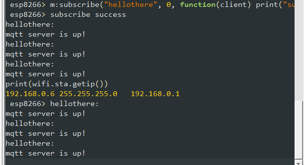
I have a node-red setup with text-to-speech, and a ping to my MQTT server provides and audible warning. It also sends an email to my personal account. I would have sent an SMS to my phone, as I have a second phone with an old SMS server on it (no need for external accounts). Just cannot find where I put that phone (DOH!). In any event, works a treat with vanilla code.

The problem is I have tried getting the light-sleep mode working to try to get as much oomph out of the batteries (to cover off most of the night). BUT. But, it seems the wake function is not so reliable. I can get it to wake not long after it sleeps, a couple to three times but, with a light-sleep function, it seems to work for a couple of times – then naught, stays asleep.

I have a LWT set up so the WIFI on the board is getting turned off (since the LWT is reported by the MQTT server). With a little too strenuous waving you can get thang to reconnect to the WIFI and report movement at least once, maybe half a dozen times, buth then goes to sleep and never wakes (or really I am not going to wait for the very long and boring timeout that has been set).

I note the example code loves GIO02 (which is the BUILTIN_LED on the D1 R2). I have also tried various other GIO, assuming it may be problematic on some IO and not on others. There is a warning not to use GIO16, which I heeded.

Without a sleep function, I the thang can tick over and ping the node-red flow I have set up reliably, with no obvious problem with false alerts. So I relented and went with that.

I have decided to set it up to run all night on my desk, facing away from seductive heat signatures. I have a “herald” message, and I assume the battery will die into the night, so I’ll see a LWT. That way I can gauge how long an approach that does not use any sleep mode will provide movement detections.

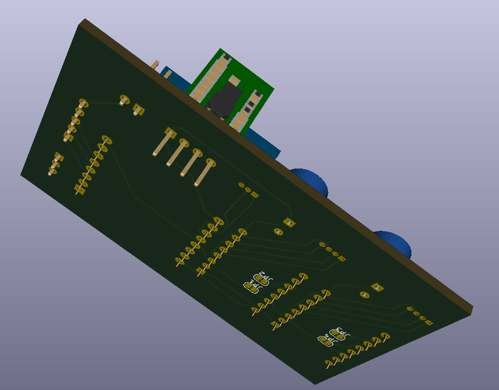
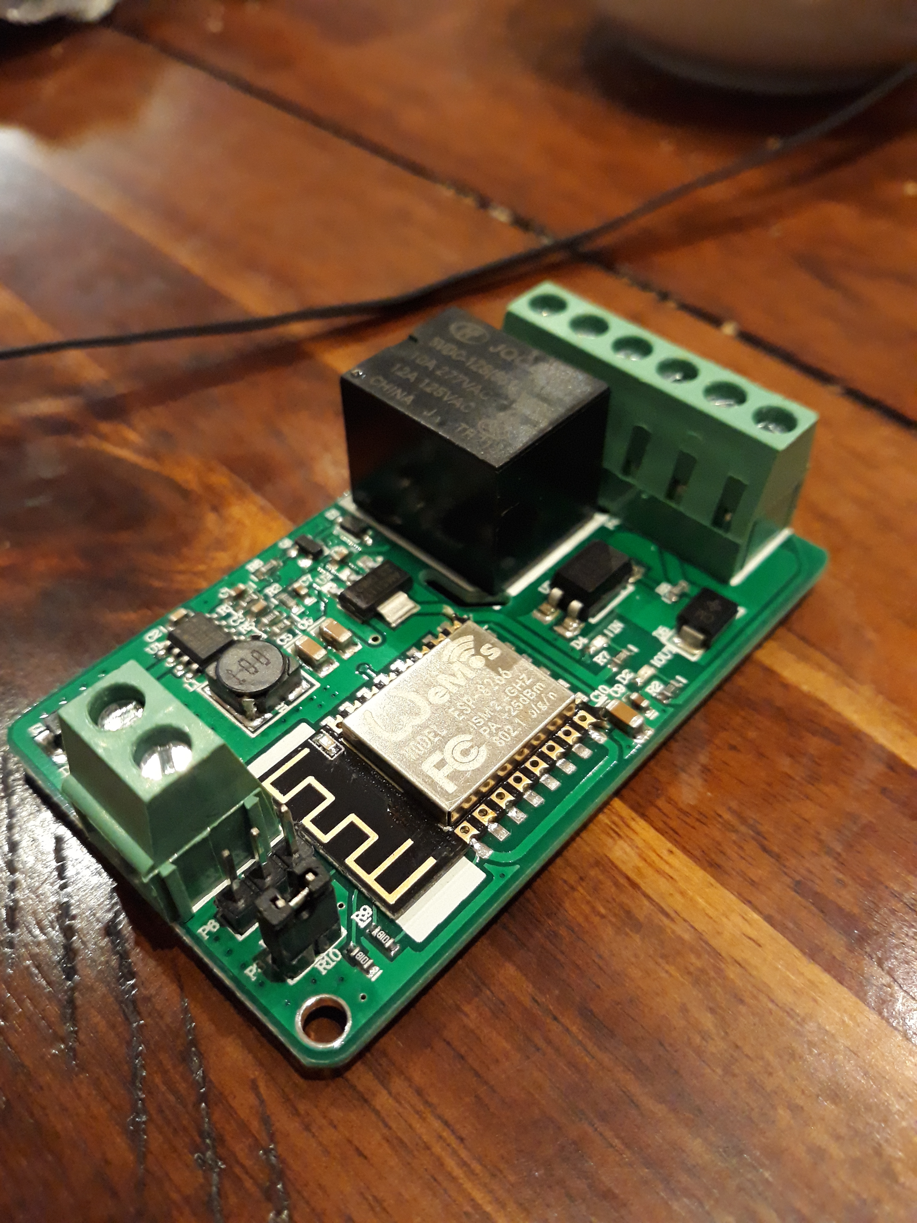
Speaking about opensprinklette, I am half way through designing a cleaner board. But then found a not bad board on Aliexpress. The (take a deep breath if you’re going to say it) LILYGO® T-Relay ESP32 5V Relay Module 8 Channel With Optocoupler Isolation (if you’re turning blue … I told you so!).

I might have a look at a port of opensprinklette to that board, though it would need a separate 24VAC to board DC conversion.

UPDATE

Ran the simplified code all night. Only reading the PIR and then sending an email if high. Ran for about 4.5 hours, which was probably okay for the job – it really only had to work for one or two nights. So, with a recharge in between and a half the night covered, goodenuff.

The problem, and as many people are reporting for this PIR, quite regular false detects. False since I had it running on my desk, in the dark, facing the back panel of a bookcase. So darkened room. No movement. In the morro, chockablock my email was with “Boo! Movement detected” messages sent from node-red.

The “missing” false alarms when running initial tests appears simply because the false alerts were intermittent, and the initial bench tests were short runs.

I thus dropped the ESP8266 based approach for an ESP32 based, as the ESP32 SDK seemed simpler to sort. However, two problems. One, the WEMOSBAT board seemed not to charge the battery (I have one on my Manual PnP for a wireless peddle that seems fine). The other, I can happily get the dang thing to sleep, but never wakes, though that may be the problem with the board charging or the 5v circuit.

Fence is up now, no need to proceed, BUT I will try another WEMOSBAT board to see if I’ve got a dud board or a dud battery.

Fiddling

Posted in CNC, Design Musings, ESP8266, Freerouting, Hardware, KiCAD, OpenSprinklette on April 19, 2021 by asteriondaedalus

This 3D stuff in KiCAD is fantastic. Found a Wemos D1 R2 model and played with modelling up the opensprinklette V1.2 board thus:

Needs some work. Have to re-design the Wemos D1 R2 model I found, since it doesn’t appear KiCAD ready. The sockets are wrong positions. I also want to find terminal blocks closer to what I am actually using. Then there is the other bits, including the quad relay board. Will be a fun exercise to learn how to build 3D models for KiCAD I think.

Next steps, XY that is

Posted in CNC, Design Musings, ESP8266, Freerouting, Hardware, KiCAD, USB Microscope XY bed on April 18, 2021 by asteriondaedalus

So, as I suspected, there is no schematic component for the MP6500 Pololu board. Not a problem as I have the drv8825 lib so I have just copied it as the MP6500 and made the minor mods required. The Pololu site includes the STEP file for the MP6500 module so all very VERY good.

Still some fiddling but here’s V0.3:

So above we can see some changes. With the MP6500 there was the option of using dual dip switches for each motor driver to set the step size, but I opted for jumpers on the bottom. They come hard coded to finest step size and you cut tracks to drop back to full steps. I’ll work out the best mode for the XY platter with the prototype setup.

The too-long pins jutting out are because I will literally be using a 4 pin header on a Pololu 5V up/down regulator and will need trim the pins.

I did grab the step file for the header to “snip” the pins, but rotten FreeCAD will import the step files but refuses to convert to a solid and so cannot “snip” pins and then export a variant. I will have to look into that, since I am still to look at design my own 3D models for importing into KiCAD – as an exercise. You can see more of the detail below.

I will be using the 2123, which is the fixed 5volt unit. So you can pump between 2.7V to 11.8V to get 5V out. So, a standard 9V battery will be fine. These are the regulators I have been using on my openspriklette modules and work great.

So much fun this board. I found I had an error in the schematic, that didn’t jump out until I laid tracks (I had duplicated a couple of global labels but fixed that). I also rearranged some of the pinouts because of the physical board layout, to drastically reduced tracks complexity and use of vias is down to zero.

Just waiting now on MP6500s to turn up, to allow the prototyping to begin.

Yep, the regulator is in the way of the USB port on the D1 mini. I am in two minds here as I am probably not powering by the USB in any event. In any event, not sure it makes sense to program the D1 mini while inserted, because of the pins usage. I will mull over that fine detail for a time.

What was that?

You want to get to the USB port? Gawd you’re bossy.

So, where we’re at, while waiting on the prototyping work, is ta da! Call it V0.4.

Now, still TBD, is whether 2123 is apt for power conditioning on this when using the steppers. The size of the steppers probably fine (they are tiny). Not big on power circuits is me. The fun bit is I have a draw of the various 3.3V, 5V and 9V versions of this Pololu regulator thingy, but take care you don’t take them out of their packaging – the freaking things are not marked so you can’t easily tell them apart.

XY micro platter for USB Microscope

Posted in CNC, Design Musings, ESP8266, Freerouting, Hardware, KiCAD, USB Microscope XY bed on April 16, 2021 by asteriondaedalus

When using my USB microscope, I am finding big fat fiddly fingers are a nuisance, tweezers some help, but fine grain motion is best.

So, what about an XY micro platter?

Well, that is possible because you can buy exactly that from Aliexpress, really bits salvaged from cameras.

Voila!

And, fortuitously, I over bought drv8825 modules, so according to LastMinuteEngineers:

Just some wiring up and we can experiment.

In principle, for example, the setup will tend to look like the following:

It just needs something 3D printed to mount it, probably clipping onto the post so its removable. Some fun in FreeCAD or OpenSCAD for sure!

For the record, some useful info from the Aliexpress store:

  • Phase resistance: 5 ohms
  • Step angle: 18°
  • Phase voltage: 5V
  • Current: about 100mA

Now I know what you’re thinking, how on earth do you detect end stops. I have a cunning plan …

… to hand build miniscule SPST “button” surfaces. Just need surfaces in or close to contact, plenty to choose from:

Could also play, with conductive PLA, I suppose:

There’ll obviously need to be a little experimentation … mwahahahahah! Where’s Igor when you need him.

The trick might be to use a couple of rotating controls, based on the KY-040, for controlling the XY position:

Of note, the KY-040 comes with a push switch built in:

Using the Wemos D1 mini also leaves it open for WiFi, but not USB based, “remote” control – aiming to use most all available GPIO. BUT, notice the problem? Wemos D1 mini has 11 GPIO ports.

Sign up for RandomNerdTutorials @ https://rntlab.com/login/

Noting, according to Pololu, the minimal drive configuration for the drv8825 is:

Noting the A0 pin will be used, since I need a rate multiplier for the KY-040 sensors – to flip between fine and coarse movements. Having a pot on the A0 line is perfect for that.

  • 2x 2 pins for controlling the XY motors
  • 2x 2 encoder pins for a KY-040 for each axis (two dials, one for each axis)
  • 4 pins for XY min/max end stops
  • 1 analogue pot for rate multiplier for axis

So 11!

NO!

12 GPIO pins!

Arrrrrrgggghhhhh!

And 1 analogue pin.

DOH! Only have 11 GPIO pins.

Hmmm.

Ah! So, looks like I can save pins by putting a toggle button and then using only one KY-040 and giving up two end stops. So, something like:

  • 2x 2 pins for XY motors
  • 2 encoder pins for a single KY-040 to be shared (one dial with X or Y mode)
  • 1 pin for toggle switch, to toggle KY-040 between XY axis
  • 2 pins for XY min only end stops
  • 1 analogue pot for rate multiplier for axes

So 9 GPIO pins and 1 analogue pin. Looking like then the TxRx can be left open.

So, the button press of the KY-040 will do fine, each press will toggle between X then Y mode and back again. Or could use click versus click and hold. That will be the meat of the experimentation.

There is an apparent quirk in that the technical data for the KY-040 says 5V, but people are driving it with 3.3V and appears fine. Probably makes sense since there are discretes inside the sensor and so 3.3V may well be within margins.

The rate multiplier for the axis is required, especially if the micro stepping is used, so that coarse and fine adjustments are provided. At the finest, you think that 1 step per encoder tick might be the go, but that depends ultimately on the resolution. A log scale might be appropriated.

Perfect, we have all the info we need, and assuming the mini is happy giving up all its GPIO for this.

As an appetiser, I have drafted a V0.1 of the board, once I sort out some issues with the design while prototyping. The 6pin DIP are actually 3 spst dip switches, so I need source step files for those. I notice the search function in KiCAD, when selecting footprints, is missing. So it’s a real pain trying to trawl through to find even things like a footprint for a 100uf 50V electrolytic it seems.

The motor pins are currently using a 1.27mm spaced vertical connector, as I have gauged that 1.27mm is the pin spacing of the pins on the motors. They won’t be jumpered though, I just need sort using a padded footprint. I will solder the wires direct.

Okay, so a little fiddling and V0.2. Only because of the “art” but I need to work out if there is a step file for the 100uf 50V (really Capacitor_THT:CP_Radial_D8.0mm_P3.50mm) lying down.

And, with a little more poking around on the Net plus fiddling with KiCAD options, voila!

Obviously. you might scrunch it up more by giving up on the dip switches for the step size. So expect final board to be different again. Just having fun with KiCAD as I had to hand build the 3D model for the dvr8825 from sources, so I am getting more and more impressed with KiCAD as I was able to discover that without reading the manuals or watching videos. Plus finding step sources has been useful, though the next step is go through the process of building my own 3D files. The one that might be the exam question is the electrolytic caps. I just rotated and stretched and translated a default cap to give the feel of the result. It does bug me the leads of the caps are poking out and not bent and in there pads. It’s only cosmetic but it also is a little learning experience which is fun.

Still a little queasy about all those GPIO pins … it’s tight.

Still, all indications are that while the ESP8266 has 17 GPIO pins (0-16), you can definitely use 11 of them. The 6 pins (GPIO 6 – 11) are used to connect the flash memory chip so they are out. GPIO 1 and 3 are used as TX and RX of the hardware Serial port (UART), so in most cases, you can’t use them as normal I/O while sending/receiving serial data. We’ll just be giving up the UART and running from dials or remotely over Wifi on the finished board. That’s why the prototyping will be most important.

Of course, while we’re at it, we have to note the steppers are 5volt and the minimum drive voltage on dvr8825 is 8volt, so there may still be a back flip on the driver section. And really MP6500 are the ticket (Pololu again), I just don’t happen to have any in my drawers at the moment. Serve me right for crashing ahead with the process, but hey, we call that Agile (TM) don’t we, but only minor changes to the board once I source the libraries for the MP6500.

So, back to the drawing board with:

Doesn’t break to pin count, but now have to put an order in. So local purchase made to expedite the project, when I finalise the board I will probably do a bulk buy from Aliexpress and sell 10 or so units to recover costs.

Modifying the ESP-01 programmer

Posted in ESP8266, Hardware on April 15, 2021 by asteriondaedalus

So, if you were slow like me and did not buy an ESP-01 programmer with a switch, to switch in and out of programming mode, there are a raft of options to fix that.

One option is just solder on a wire thus:

Another is a push button and a couple of wires, with the button glued to the end thus:

I opted to by a box of dip switches of various sizes, to have handy, and simply used a SPST dipswitch thus:

Much neater and more straight forward a hack.

To ESP or not to ESP, that is the question

Posted in ESP12EBEE, ESP8266, ESPHome on April 6, 2021 by asteriondaedalus

So, I have been putting older development boards up on Ebay to clear out some of my drawers of things I don’t use no more … OH I don’t ever use no morrrrRRREEEeeee!

To that end, I cleared out a batch of items as lucky dips, notably:

Lucky Dip #1
Lucky Dip #2

Note that pesky XBee form factor popping up?!

When I did also grab my dusty rover hack, I had forgotten I had been running a DFRobot Romeo V1.0 with XBee PRO widget attached.

I was using a Bluetooth XBee, I also noticed “The Beast” were a little dusty.

Certainly can’t bear to get rid of that workhorse.

But if I get rid of the Bluetooth XBee, then what? It occurred that mixing ESP chips, with their WIFI smarts, and AVR together is a great combo for robotics.

I thought someone must have snuck an ESP chip of some sort onto an XBee form factor.

Sure enough someone did. Came up with a four layer board and was charging USD$25 odd for the flaming thing (a crazy AUD$34 so why not buy a RaspingDoodleburry Pi Zilch?).

Opted to borrow the idea and re-do it as a 2 layer board, so voila!

So that’s a direct port of the Casco Logix ESPBee V1.1, except neatly 2 layered and thus a cheaper prospect of the bat.

But you have to note that the XBee Pro does also lift additional pins off the XBee form factor out to posts. So I will need make a second version that brings out additional pins.

Go figure, that makes sense, since there is also then a range of baseboards to use:

To name a few. But, there is one that makes very good sense to match to, being:

So I am also dabbling with an ESP12EBEE V2.0. The ESP12EBEE V1.0 only has the Rx/Tx brought out, while the V2.0 tries to support as many pins as possible. At the moment, I just brought the ADC out to XBee pin 11. I will dabble with a means to try to optionally assign the ADC at least. That will be a little trickier.

Again, a 2 and not 4 sided board. To keep the unit price down.

Now, whether you use this to drive previously XBee oriented base boards using ESPHome might well and truly be up to you.

One thing I did not do is map this to the XBee Pro shield. That might either result in a V2.1 to tune it to my needs on “The Beast”!

Of course, nothing is easy. These modules need to be programmed, so it makes sense to also build a separate programmer.

Back to KiCAD!

So, a small board to take a few components, two momentary SPST and a few discretes.

The trick is I will use a Sparkfun 3.3VDC FTDI basic breakout, so a 6 post connection is all that is needed.

Although, there are a range of ESP Programmers already out there to consider:

Most all probably borrowing from nodemcu devkit.

Noting the basic problem looks like this:

Where as the original ESPBee schematic is:

Pegaleg

Posted in ESP8266, MQTT, node-red, OpenSprinklette on November 11, 2018 by asteriondaedalus

So, one file I had fun getting off my laptop was the source for the parser for the google calendar event titles.

The titles, as discussed previously, would be a list of sprinkler group or unit callouts.

I managed to ssh onto the laptop from my desktop to lift anything I wanted before I trashed the laptop with a clean Debian install.

While waiting for the install, I opted to tart up the parser with some sanity.

The problem for the distributed opensprinklette design is that there is no editor per se to police the entries in the google calendar event title. So, if any unwanted text is in the title, the parser running on the node-red server will drop the lot. Harsh I know, but the distributed nature of this entails some trade-offs.

So, I did add some smarts to avoid sending repeated call-outs to a sprinkler. A burst of call-outs will go out once the event title is parsed. The ESP8266 gadgets don’t mind if a single sprinkler is pummelled – it simply results in the time starting from the last received call-out – which won’t be that many milliseconds behind the first.

Still, to opt for a defensive scheme meant testing for a call-out in the return from the scan of the line before adding it to the return. Simples tick!

So, even if the user pummels the title of the event with multiple call-outs to the same sprinkler, the parsed response will only contain a single call-out.

So something like this in the google calendar title:

group1=1;group1=[1];group1=[2,2,2,4,4,4,4,1,1,1,3]

will return the following in the node-red response (prior to fully concatenating into a MQTT topic):
[
"group1/1",
"group1/2",
"group1/4",
"group1/3"
]

Opensprinklette Single!

Posted in Embedded, ESP8266, Hardware, OpenSprinklette on October 15, 2018 by asteriondaedalus

20181015_172706

So, found some info on the board.

Where I thought there was dual throw relay, it’s even better since the second set of terminals are a optocoupler. So, that would be grand for either of a rain gauge input, the audio trigger for dog barking, the flow rate sensor et cetera.

It is otherwise an WeMOS ESP-8266.

What is crazy is that the board thinks of everything and has bidirectional zeners on power and optical inputs so its really for light-industrial applications. That is, includes Transient Voltage Suppressors.

AND! One of the terminals is a regulated 5V output! Just exactly enough for the sound level detection for the dog barking.

Loving it!

Small steps

Posted in Embedded, ESP8266, IOT, MQTT, node-red, NodeMCU, OpenSprinklette, WEMOS D1 R2 on August 7, 2017 by asteriondaedalus

I have roughed a node-red config node and it’s visible counterpart.  I decided to call wemos nodes “sectors” – since the usual rort is to call a single channel on an irrigation controller, controlling a single solenoid, a zone.

I have set up for 4 sectors each using a WeMOS D1R2 with a quad relay shield.  That provides up to 16 zones (4 per WeMOS).

You need to mod the relay shield with a couple of pullup resisters.  This is to get around a design shortfall on the WeMOD D1R2.

I am using a protoshield in between the WeMOS and the relay shield to allow for fidgeting with design changes. I added a four position dip to set the zone id BUT I dropped that in favour of the config node concept.

That gives me back 4 pins for GPIO. The problem is the out and out lie that the WeMOS is a Uno form factor. The ESP8266 has to cheat by using the same GPIO pins across a couple of Arduino socket pins.

I will add the rain gauge input later.

The idea is an input line such as the following as the title of the google calendar event:

sector1=1,sector3=4,sector2=0,sector3=1

The line above shows you some of the input features I will aim for, being:

  • You don’t need to nominate all four sectors or even all four individual zones of a sector.
  • You can order the sectors in any order.
  • The zones per sector are number 0..4 with 0 being the global all on/off id for all 4 zones on the addressed sector.

I did think about using JSON as input but the problem is that if you have two tokens the same then the object construction takes the later value in the line for the key.  Oh well.

For this to work you attach two google calendar event sniffers, one to flag the start of an event and one to flag the end.  Both feed into the opensprinklette-configurator to decode the events into MQTT calls to the 4 WeMOS D1 R2.

Of note, the configurator maps between chipid() and sector# (and back again) so planning the sprinkling can be in people-talk (relatively speaking).  At least you don’t have to remember which WeMOS chipid() was allocated to what sector.

Of course, there are quirks to do with the distributed system.  There will be a watchdog on the WeMOS to automatically turn off the water to a zone after 45min.  To plan out longer watering you will need back to back calendar events (shorter than 45min to avoid the watchdog).  If that is offensive please send money to help me pay the water bill of a runaway commercial setup ($3,000 in fact).

The other option I guess is send the duration to the WeMOS node and let it do the countdown.

I will play with a couple of timing approaches to see what is most robust – given you could have the ISP gateway drop out, the node-red crash, the emqttd crash, the OPiZ drop of the network.  Not to mention, google calendar hickups – I occasionally get a baulk around credentials lapsing that somehow comes good again.  Oh and of course, the WeMOS could also behave badly.

All in all needs a good bashing to help weed out nuisances.

Back to work

Posted in ESP8266, Lua, MQTT, node-red, OpenSprinklette, Orange Pi, WEMOS D1 R2 on August 5, 2017 by asteriondaedalus

So, at last, now that the OPiZ setup saga is over (fingers crossed) we begin over.

I built a new nodemcu firmware for the WeMOS to include:

  • bit
  • end user setup
  • file
  • GPIO
  • MQTT
  • net
  • node
  • RTC Time
  • SNTP
  • timer
  • UART
  • Wifi

A few coding snippets later and  the WeMOS can catch the mqtt topic running on the OPiZ feed by the node-red on the OPiZ.

wemos

So, I can now parcel up the OPiZ as the house server and tidy up the sprinkler system.

I did note that the WeMOS did not come up first time I bombed the firmware.  That was sorted (it seemed) by selection the 4MB Flash option on ESP8266Flasher.  The ESP-12E on the WeMOS has a 4MB flash and I noted that there is a branch of the nodemcu frozen in time now for the 512kB chips – so go with the master branch if you have the WeMOS D1 R2.

I did also manage to break a hoodoo now that nodemcu does away with autoconnect for the MQTT.  The timer callback scheme works a treat.  I can reboot the OPiZ and the WeMOS will reconnect once emqttd is up and running again.  Of course, I have a LWT setup so that the emqttd server will tell the node-red if the WeMOS drops off the channel.

This is getting exciting now.