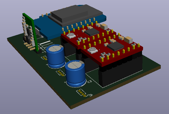
This 3D stuff in KiCAD is fantastic. Found a Wemos D1 R2 model and played with modelling up the opensprinklette V1.2 board thus:
Needs some work. Have to re-design the Wemos D1 R2 model I found, since it doesn’t appear KiCAD ready. The sockets are wrong positions. I also want to find terminal blocks closer to what I am actually using. Then there is the other bits, including the quad relay board. Will be a fun exercise to learn how to build 3D models for KiCAD I think.
So, as I suspected, there is no schematic component for the MP6500 Pololu board. Not a problem as I have the drv8825 lib so I have just copied it as the MP6500 and made the minor mods required. The Pololu site includes the STEP file for the MP6500 module so all very VERY good.
Still some fiddling but here’s V0.3:
So above we can see some changes. With the MP6500 there was the option of using dual dip switches for each motor driver to set the step size, but I opted for jumpers on the bottom. They come hard coded to finest step size and you cut tracks to drop back to full steps. I’ll work out the best mode for the XY platter with the prototype setup.
The too-long pins jutting out are because I will literally be using a 4 pin header on a Pololu 5V up/down regulator and will need trim the pins.
I did grab the step file for the header to “snip” the pins, but rotten FreeCAD will import the step files but refuses to convert to a solid and so cannot “snip” pins and then export a variant. I will have to look into that, since I am still to look at design my own 3D models for importing into KiCAD – as an exercise. You can see more of the detail below.
I will be using the 2123, which is the fixed 5volt unit. So you can pump between 2.7V to 11.8V to get 5V out. So, a standard 9V battery will be fine. These are the regulators I have been using on my openspriklette modules and work great.
So much fun this board. I found I had an error in the schematic, that didn’t jump out until I laid tracks (I had duplicated a couple of global labels but fixed that). I also rearranged some of the pinouts because of the physical board layout, to drastically reduced tracks complexity and use of vias is down to zero.
Just waiting now on MP6500s to turn up, to allow the prototyping to begin.
Yep, the regulator is in the way of the USB port on the D1 mini. I am in two minds here as I am probably not powering by the USB in any event. In any event, not sure it makes sense to program the D1 mini while inserted, because of the pins usage. I will mull over that fine detail for a time.
What was that?
You want to get to the USB port? Gawd you’re bossy.
So, where we’re at, while waiting on the prototyping work, is ta da! Call it V0.4.
Now, still TBD, is whether 2123 is apt for power conditioning on this when using the steppers. The size of the steppers probably fine (they are tiny). Not big on power circuits is me. The fun bit is I have a draw of the various 3.3V, 5V and 9V versions of this Pololu regulator thingy, but take care you don’t take them out of their packaging – the freaking things are not marked so you can’t easily tell them apart.
When using my USB microscope, I am finding big fat fiddly fingers are a nuisance, tweezers some help, but fine grain motion is best.
So, what about an XY micro platter?
Well, that is possible because you can buy exactly that from Aliexpress, really bits salvaged from cameras.
Voila!
And, fortuitously, I over bought drv8825 modules, so according to LastMinuteEngineers:
Just some wiring up and we can experiment.
In principle, for example, the setup will tend to look like the following:
It just needs something 3D printed to mount it, probably clipping onto the post so its removable. Some fun in FreeCAD or OpenSCAD for sure!
For the record, some useful info from the Aliexpress store:
Phase resistance: 5 ohms
Step angle: 18°
Phase voltage: 5V
Current: about 100mA
Now I know what you’re thinking, how on earth do you detect end stops. I have a cunning plan …
… to hand build miniscule SPST “button” surfaces. Just need surfaces in or close to contact, plenty to choose from:
Could also play, with conductive PLA, I suppose:
There’ll obviously need to be a little experimentation … mwahahahahah! Where’s Igor when you need him.
The trick might be to use a couple of rotating controls, based on the KY-040, for controlling the XY position:
Of note, the KY-040 comes with a push switch built in:
Using the Wemos D1 mini also leaves it open for WiFi, but not USB based, “remote” control – aiming to use most all available GPIO. BUT, notice the problem? Wemos D1 mini has 11 GPIO ports.
Noting the A0 pin will be used, since I need a rate multiplier for the KY-040 sensors – to flip between fine and coarse movements. Having a pot on the A0 line is perfect for that.
2x 2 pins for controlling the XY motors
2x 2 encoder pins for a KY-040 for each axis (two dials, one for each axis)
4 pins for XY min/max end stops
1 analogue pot for rate multiplier for axis
So 11!
NO!
12 GPIO pins!
Arrrrrrgggghhhhh!
And 1 analogue pin.
DOH! Only have 11 GPIO pins.
Hmmm.
Ah! So, looks like I can save pins by putting a toggle button and then using only one KY-040 and giving up two end stops. So, something like:
2x 2 pins for XY motors
2 encoder pins for a single KY-040 to be shared (one dial with X or Y mode)
1 pin for toggle switch, to toggle KY-040 between XY axis
2 pins for XY min only end stops
1 analogue pot for rate multiplier for axes
So 9 GPIO pins and 1 analogue pin. Looking like then the TxRx can be left open.
So, the button press of the KY-040 will do fine, each press will toggle between X then Y mode and back again. Or could use click versus click and hold. That will be the meat of the experimentation.
There is an apparent quirk in that the technical data for the KY-040 says 5V, but people are driving it with 3.3V and appears fine. Probably makes sense since there are discretes inside the sensor and so 3.3V may well be within margins.
The rate multiplier for the axis is required, especially if the micro stepping is used, so that coarse and fine adjustments are provided. At the finest, you think that 1 step per encoder tick might be the go, but that depends ultimately on the resolution. A log scale might be appropriated.
Perfect, we have all the info we need, and assuming the mini is happy giving up all its GPIO for this.
As an appetiser, I have drafted a V0.1 of the board, once I sort out some issues with the design while prototyping. The 6pin DIP are actually 3 spst dip switches, so I need source step files for those. I notice the search function in KiCAD, when selecting footprints, is missing. So it’s a real pain trying to trawl through to find even things like a footprint for a 100uf 50V electrolytic it seems.
The motor pins are currently using a 1.27mm spaced vertical connector, as I have gauged that 1.27mm is the pin spacing of the pins on the motors. They won’t be jumpered though, I just need sort using a padded footprint. I will solder the wires direct.
Okay, so a little fiddling and V0.2. Only because of the “art” but I need to work out if there is a step file for the 100uf 50V (really Capacitor_THT:CP_Radial_D8.0mm_P3.50mm) lying down.
And, with a little more poking around on the Net plus fiddling with KiCAD options, voila!
Obviously. you might scrunch it up more by giving up on the dip switches for the step size. So expect final board to be different again. Just having fun with KiCAD as I had to hand build the 3D model for the dvr8825 from sources, so I am getting more and more impressed with KiCAD as I was able to discover that without reading the manuals or watching videos. Plus finding step sources has been useful, though the next step is go through the process of building my own 3D files. The one that might be the exam question is the electrolytic caps. I just rotated and stretched and translated a default cap to give the feel of the result. It does bug me the leads of the caps are poking out and not bent and in there pads. It’s only cosmetic but it also is a little learning experience which is fun.
Still a little queasy about all those GPIO pins … it’s tight.
Still, all indications are that while the ESP8266 has 17 GPIO pins (0-16), you can definitely use 11 of them. The 6 pins (GPIO 6 – 11) are used to connect the flash memory chip so they are out. GPIO 1 and 3 are used as TX and RX of the hardware Serial port (UART), so in most cases, you can’t use them as normal I/O while sending/receiving serial data. We’ll just be giving up the UART and running from dials or remotely over Wifi on the finished board. That’s why the prototyping will be most important.
Of course, while we’re at it, we have to note the steppers are 5volt and the minimum drive voltage on dvr8825 is 8volt, so there may still be a back flip on the driver section. And really MP6500 are the ticket (Pololu again), I just don’t happen to have any in my drawers at the moment. Serve me right for crashing ahead with the process, but hey, we call that Agile (TM) don’t we, but only minor changes to the board once I source the libraries for the MP6500.
So, back to the drawing board with:
Doesn’t break to pin count, but now have to put an order in. So local purchase made to expedite the project, when I finalise the board I will probably do a bulk buy from Aliexpress and sell 10 or so units to recover costs.


You must be logged in to post a comment.